Geomembrane Panel Layout for Irrigation Ponds: From Roll Delivery to As-Built Records
114
0
A geomembrane panel layout should show how the liner will be deployed, joined, inspected, and handed over. This guide explains what to put on the drawing and how to record changes made during installation.
- Geomembrane Panel Layout for Irrigation Ponds: From Roll Delivery to As-Built Records
- Start with the Geometry the Crew Will Actually Line
- Link Each Installed Panel to Its Source Roll
- Place Seams Where the Crew Can Make and Inspect Them
- Plan Panel Placement and Release for Cover
- Update the Drawing When the Layout Changes on Site
- Use the Layout to Compare Quotations
Geomembrane Panel Layout for Irrigation Ponds: From Roll Delivery to As-Built Records
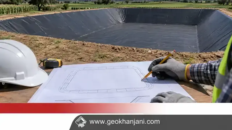
Illustrative reconstruction of an irrigation pond and its layout drawing.
Two irrigation ponds can have the same lined area and require different installation plans. One may have a straight perimeter and a clear working area. The other may have an outlet near a corner, an irregular slope, and room for only one roll at the crest. The area estimate tells the buyer how much liner the design calls for. The panel layout shows where the crew will place that liner, where it can make and inspect the seams, and which sections can be released for cover.
A useful layout lets the installer find the next panel, the inspector locate a seam or repair cited in a report, and the earthworks crew see where it can begin placing cover. All three teams should use the same drawing revision and panel and zone identifiers. At the daily briefing, identify the drawing revision by date and replace outdated copies before the next work stage begins.
Start with the Geometry the Crew Will Actually Line
Compare the approved plan and sections with the prepared pond. Mark the floor, slope toes, crest, anchor trenches, pipe penetrations, and concrete structures. Confirm the developed distance along the slope. A horizontal plan dimension gives only the horizontal projection, so measure the surface distance between the floor and the anchor trench. Include the allowances in the approved details for seams, transitions, and anchorage.
Walk the perimeter before finalizing the cutting schedule. An access ramp may occupy space reserved for roll staging, or a pipe may have been installed closer to a corner than shown on the original drawing. Record discrepancies and refer them to the project lead before cutting. If a protective geotextile layer is specified, mark where it begins and ends so the two installation crews can coordinate their work.
Link Each Installed Panel to Its Source Roll
A roll number identifies material delivered to site. A panel number identifies a piece installed in the pond. When several pieces come from the same roll, give each piece its own panel number and retain the source roll number in the schedule. This lets the inspector locate each piece independently and trace it back to the delivery record.
Record the material type, nominal thickness, actual roll dimensions, and intended position of each panel. Check that the schedule reflects the geomembrane specified for the project. In the quantity sheet, separate net liner area from joining and termination allowances. Record offcuts separately so the team can see which pieces may be reused under the approved layout.
Consider a straight floor strip 18 m wide. Five 4 m panels placed side by side with four hypothetical overlaps of 0.15 m cover 19.40 m before edge trimming. This calculation checks coverage across the floor strip. Measure slopes, corners, anchorage, and spare material separately. Use the overlap stated in the project specification for the actual installation.
Place Seams Where the Crew Can Make and Inspect Them
Review seam direction with the designer and installer, especially on slopes. Construction guidance commonly aligns seams in the direction of maximum slope, subject to approved drawings and specifications. Review grade changes separately. A seam that appears straight in plan may cross a break in slope or enter a recess where the equipment cannot follow it easily.
Draw the proposed seams and junctions alongside pipe penetrations and other termination details. If a seam passes close to an outlet, check that the crew can make the connection and the inspector can reach the relevant areas. Where a pipe boot is used, identify the connection to the liner and the connection around the pipe in the records. See the GeoKhanjani guide to sealing pond pipe penetrations.
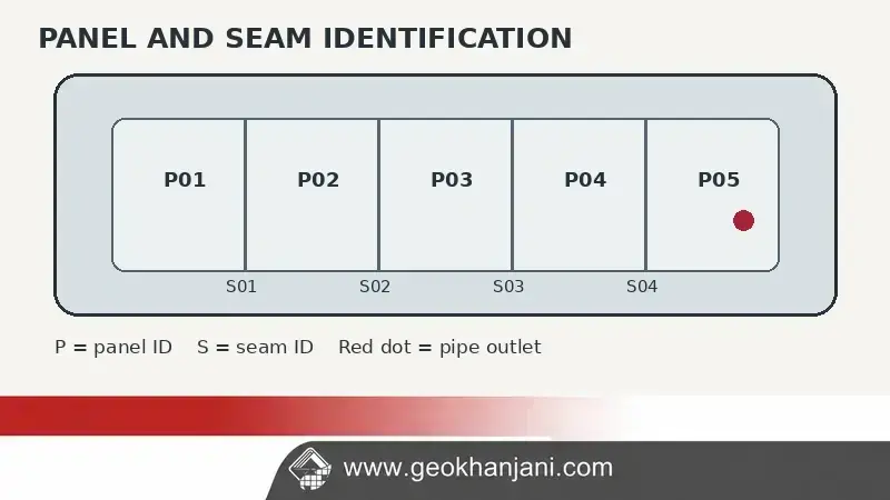
Conceptual panel schedule and seam map. Diagram is not to scale.
Plan Panel Placement and Release for Cover
The deployment sequence should show where rolls will be staged, which zone will be lined first, and how the next crew will reach unfinished seams. At the end of a shift, record panels already placed, seams awaiting inspection, and areas formally released for cover. A panel may be complete while the adjacent outlet still needs inspection. If both appear under one status, the cover crew cannot tell where work must stop.
On the dated status map, outline the area released for cover and record who approved it. If the eastern floor has been cleared while Outlet 2 remains open, show the boundary on the plan the earthworks crew uses. Keep the map and inspection results with the pre-cover geomembrane handover checklist.
Update the Drawing When the Layout Changes on Site
Suppose a corner was planned as one piece, but the verified field geometry requires a different cut. Submit the revised detail through the project change procedure before cutting. After installation, record the new panel and seam locations on the as-built drawing. Retain the earlier revision so the supervisor can tell which plan was used when each stage was completed.
Give every repair an identifier. Locate it against a seam, panel edge, or survey point. Use the same identifier on the photograph, repair report, and follow-up inspection result. Where electrical leak location is part of the quality plan, the guide to preparing a pond for an electrical leak survey explains what to record when some areas are exposed and others have been covered.
Example of an as-built status map with a repair marker and release boundary.
Use the Layout to Compare Quotations
Give bidders the same plan, slope sections, penetration details, and proposed work zones. Ask them to state the liner quantity, assumed roll dimensions, field seaming scope, and inspection scope separately. Confirm who provides the protective layer and who authorizes cover placement. If one offer assumes more field cutting or fewer inspection stages, those differences should be visible before the contract is awarded. For the material line item, consult the GeoKhanjani geomembrane pricing page in Persian.