Geogrid Installation Damage: What to Check Before Placing the Next Fill Layer
164
0
Learn how to inspect geogrid for damage, correct placement and site readiness before covering it with fill, following project specifications and manufacturer instructions.
- • Geogrid Installation Damage: What to Check Before Placing the Next Fill Layer
- • Make inspection a planned construction step
- • 1. Confirm the function before judging the installation
- • 2. Check the supporting surface and water conditions
- • 3. Look for damage while the grid remains exposed
- • 4. Verify direction, continuity and connection details
- • 5. Separate reinforcement from filtration requirements
- • 6. Plan fill placement and equipment movements together
- • 7. Recheck when fill or site conditions change
- • 8. Obtain an approved response to damaged material
- • 9. Close the inspection with evidence
Geogrid Installation Damage: What to Check Before Placing the Next Fill Layer
Make inspection a planned construction step
Once aggregate covers a geogrid, checking its position and condition becomes difficult. That makes the interval between unrolling reinforcement and placing fill an important inspection opportunity. A quick photograph is useful, but it cannot replace checking the specified product, layout and installation method. The practical question is whether the installed layer matches the approved details and can survive the next construction operation. This guide explains how to organise that check without inventing universal overlap lengths, cover depths or repair dimensions. Those requirements belong to the project documents and the instructions for the actual product supplied.
1. Confirm the function before judging the installation
Geogrids used beneath roads and geogrids reinforcing retaining structures do not necessarily follow identical design or installation rules. Start by identifying the intended function, reinforcement direction and approved layout. Our overview of geogrid applications explains the wider range of uses, while the inspection must remain specific to the current project. Check the roll label against the delivery documents and drawings. Record the product designation and batch information before cutting or placing material. A similar colour, aperture shape or advertised tensile strength does not establish equivalence. Refer any proposed substitution to the responsible designer before installation proceeds.
2. Check the supporting surface and water conditions
Inspect the surface for debris, protrusions, unexpected soft areas and conditions that differ from the approved preparation requirements. Do not assume that stretching a grid across an unsuitable area resolves the underlying problem. Where standing water, pumping or surface disturbance is present, obtain the required site assessment before covering it. The geogrid product range provides a starting point for comparing available reinforcement options; product selection does not replace assessment of the supporting ground or site drainage. Record what was observed and what corrective work was authorised. Keep unresolved ground conditions visible in the inspection record rather than marking the layer complete.
3. Look for damage while the grid remains exposed
Walk the accessible installation area and identify cut ribs, broken junctions, tears or other changes that require assessment. Examine handling points and locations where material has caught on equipment or site obstructions. Describe the damage rather than immediately deciding that it is harmless or unacceptable. Photographs should show the affected area, a scale and enough surrounding context to locate it. Record the roll reference and installation location. Visual inspection can identify obvious defects, but it cannot establish retained strength. Where performance is uncertain, the designer or manufacturer should determine whether further evaluation, replacement or repair is appropriate.
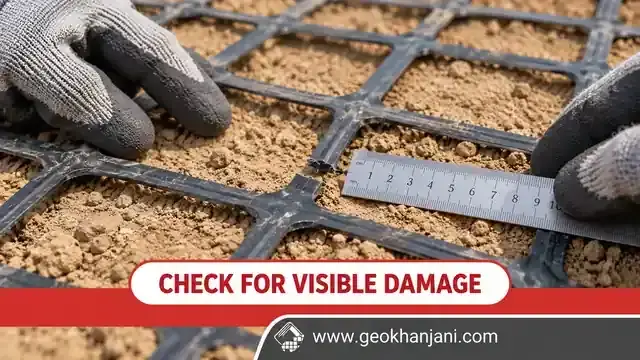 Geogrid Visual Damage Inspection
4. Verify direction, continuity and connection details
Compare the installed direction with the drawings, especially where the design relies on reinforcement strength in a particular direction. Check lengths, terminations and connections using the approved details. Do not treat a lap in a stabilisation layer as automatically equivalent to a structural connection in reinforced soil. At wall faces, corners and changes in geometry, stop and clarify missing details before proceeding. For polyester geogrid, confirm the supplied grade, reinforcement direction and connection requirements against the design rather than relying on the material name. Inspecting the grid alone cannot confirm overall wall stability. Record deviations clearly and obtain approval for any revised arrangement.
 Geogrid Orientation and Overlap Inspection
5. Separate reinforcement from filtration requirements
An open grid does not automatically provide the separation or filtration required between different soils. Check whether the design includes a separate geotextile or a specified composite product. If so, inspect that component as well, including continuity and condition. When considering connective geogrids, obtain documented construction and performance information; the product name alone does not confirm filtration capability. Adding an unspecified fabric is not an automatic improvement: it changes the installed arrangement and should be reviewed. Confirm which material faces each adjacent layer and how the components terminate. Record the actual configuration so later reviewers do not have to infer it from photographs alone.
6. Plan fill placement and equipment movements together
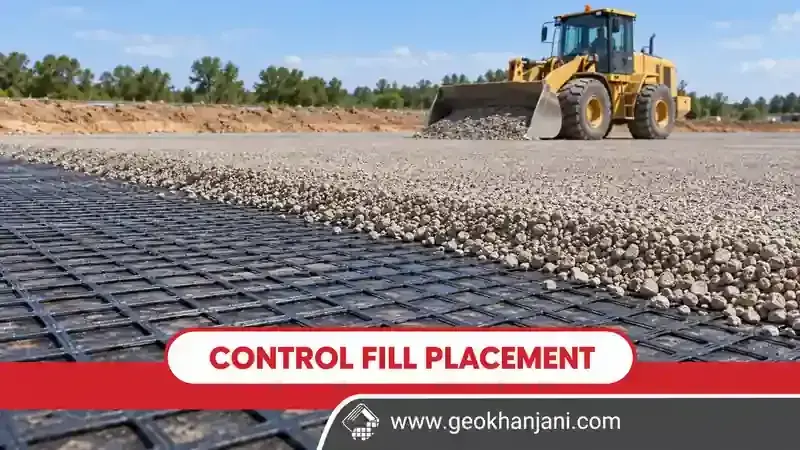
Before allowing construction traffic, confirm the required cover and operating restrictions for the specified system. Avoid assuming that permissions from another manufacturer's guide apply here. Equipment type, turning movements and construction conditions matter. Agree how fill will be delivered and spread without displacing the exposed layer. Check that operators understand the planned route and the limits of the working area. If the grid moves, wrinkles or becomes damaged during placement, stop the affected operation and reassess it. The inspection is not finished simply because the first photograph looked satisfactory. Monitor the transition from exposed reinforcement to covered layer.
7. Recheck when fill or site conditions change
Installation damage depends partly on the interaction between the geosynthetic, fill and construction process. A change in aggregate source, particle characteristics or compaction equipment deserves review rather than automatic acceptance. Confirm that delivery records match the approved material and that any required testing has been completed. For injection geogrid, as with other types, request installation guidance for the actual grade supplied and review any proposed changes in construction conditions. Record rainfall interruptions and changes in ground response. The purpose is to identify changed conditions early, before they become hidden beneath several additional lifts and harder to investigate.
8. Obtain an approved response to damaged material
Do not improvise a patch size or repair method from a photograph online. Some situations require replacement, while others may permit a documented repair compatible with the product and design. Mark the affected location and keep it identifiable until a decision is recorded. The repair instruction should specify the material, extent, orientation and inspection requirements. If covering has already occurred, agree how any investigation can be performed without creating further damage. Keep the original observation, the decision and the completed work together. A repair photograph without its approval record leaves an important gap in construction documentation.
9. Close the inspection with evidence
Use a checklist covering product identity, surface preparation, visible damage, orientation, layout, adjoining materials and readiness for fill placement. Give each item a clear outcome: accepted, correction required or information missing. Name the person responsible for closing outstanding actions. Include drawing revisions, photographs and any approved repair instructions. Before ordering additional material through GeoKhanjani, share the product code, application and documented requirements so available specifications can be compared meaningfully. Do not describe technical suitability as established merely because a quotation has been issued. A useful inspection record links the supplied material to its location, the observed condition and the authorised next step.
Schedule this review before the next crew arrives, allowing time for clarification of outstanding installation questions.