Assess geonet drainage using project conditions, not thickness alone. This guide explains flow testing, sustained loading, filter interaction and the information needed for a useful product comparison.
- • Start with the installed drainage system
- • Separate flow rate from transmissivity
- • Match the load and contact surfaces
- • Evaluate sustained loading separately
- • Review the complete filter and core assembly
- • Compare alternatives on an equal basis
- • Check collection pipes and outlets
- • Use a clearly labelled calculation example
- • Prepare an enquiry that supports a decision
- • Turn the specification into a site record
Geonet Drainage Under Load: How to Assess Flow Capacity
Start with the installed drainage system
A geonet can look open and rigid on delivery yet behave differently after burial. Soil pressure, adjacent materials, hydraulic gradient, and loading duration influence how much water the installed drainage layer can carry. Choosing by thickness alone overlooks these conditions. The practical question is whether the complete assembly can discharge the expected inflow throughout its intended service period. Begin with the application, available outlet, and loading arrangement before comparing products. GeoKhanjani’s geonet product page provides a starting point for an enquiry; project suitability still requires documented properties and an engineering assessment.
Separate flow rate from transmissivity
Flow rate per unit width describes the discharge carried by a strip of drainage material. Hydraulic transmissivity relates that discharge to hydraulic gradient. Their numerical values coincide only when the gradient equals one, using compatible units. A result measured on a steep gradient therefore cannot automatically represent a shallow installation. Request the reported quantity, units, gradient, and specimen orientation together. Where discharge does not vary proportionally with gradient, avoid extrapolating from a single transmissivity value. Compare measured flow performance at conditions relevant to the project instead of treating a catalogue number as a universal capacity. Standard Specification for Required
Match the load and contact surfaces
Normal stress compresses the drainage assembly. A test between rigid plates may produce a different result from one involving soil, geotextile, or a flexible liner. These boundaries can change how surrounding materials enter the core openings. ASTM D4716/D4716M provides a method for evaluating flow under specified conditions; citing the standard without those conditions leaves the comparison incomplete. For a geocomposite drainage system, ask whether the report covers the finished composite or only its bare core. Also record seating time, water temperature, flow direction, and the stress applied during testing. store.astm.org
 Load and Contact Surfaces
Evaluate sustained loading separately
Short laboratory measurements do not automatically establish performance over decades. Polymer drainage cores can deform progressively under sustained loading, reducing the space available for flow. The relevant question is how the proposed core behaves under the actual stress, temperature, and duration. Request supporting creep information and the basis used to derive allowable capacity. Do not select a universal reduction factor from an unrelated project. Equally, avoid applying an allowance twice when the supplied performance value already includes it. A qualified designer should document which effects are covered by testing and which require additional allowances. geosynthetic-institute.org
Review the complete filter and core assembly
A drainage core moves water along its plane; a filter controls soil migration into that drainage path. These functions must work together. Filter fabric can intrude into core openings under pressure, while unsuitable soil compatibility can restrict water entry. Selecting nonwoven geotextile by mass alone does not resolve either issue. Review soil information, opening characteristics, hydraulic properties, and the actual contact arrangement. If discharge has deteriorated in an existing installation, the geotextile clogging diagnosis guide helps distinguish filter restrictions from other drainage problems before specifying replacement materials.
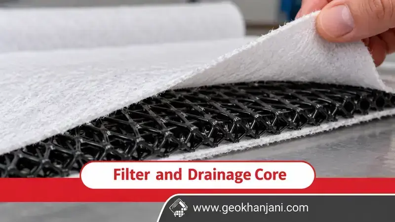 Filter and Drainage Core
Compare alternatives on an equal basis
An alternative core geometry may perform differently under the same boundary conditions, but its name does not establish superiority. Compare a conventional geonet and a three dimensional drainage geonet using consistent stress, gradient, contact surfaces, and test duration. Check whether results refer to the same flow direction and finished configuration. Ask suppliers to identify missing evidence rather than filling gaps with assumed equivalence. A comparison sheet should distinguish guaranteed specification values from typical measurements. Neither a thicker core nor a heavier composite should be accepted solely because its headline figure appears larger.
Check collection pipes and outlets
Adequate core capacity is useful only when collected water can leave the system. Inspect the transition into the collector, outlet elevation, discharge route, and provisions for inspection or maintenance. An obstructed outlet can cause backing up even when the geonet itself remains functional. Coordinate the drainage layer with the collection pipe and connection details rather than purchasing each component independently. During installation, protect the flow path from sediment, displaced fabric, and crushed connections. Record the approved layout before covering it so later maintenance does not depend on guesswork about buried components.
Use a clearly labelled calculation example
Consider a hypothetical drainage strip with a design inflow of 0.30 litres per second per metre of width. Suppose an engineer establishes an allowable capacity of 0.45 under matching project conditions. The capacity to demand ratio is 1.5. That arithmetic does not confirm acceptance: the required safety margin, inflow uncertainty, loading cases, and outlet conditions still need review. If the capacity came from a short index test, calling it allowable would be unjustified. Keep this example separate from supplier data; it is not a recommendation, product rating, or verified result for any GeoKhanjani material.
Prepare an enquiry that supports a decision
Provide the proposed section drawing, drainage length, slope, anticipated inflow, loading conditions, adjacent materials, liquid characteristics, and intended service period. Request a traceable report identifying the tested product and configuration. Include installation drawings showing overlaps, connections, and discharge points. For containment projects, assess drainage and barrier costs as separate system components. GeoKhanjani’s Persian geomembrane price page can support the liner enquiry, but it does not establish drainage suitability. Select the assembly from documented performance, then compare supply and installation costs against that agreed technical requirement.
Turn the specification into a site record
A useful specification should remain understandable when the purchasing team hands it to the installer. Identify the approved product, required orientation, applicable test conditions, and acceptance documents in the same record. Record substitutions before delivery rather than discovering a different core or fabric after installation. Where drawings require exposed edges or particular overlap details, follow the approved system instructions; generic fastening advice cannot replace them. Photograph accessible connections and retain delivery labels so the installed material can be traced to the submitted documentation.
After installation, record the actual discharge route and any deviations from the approved arrangement. This information helps future investigators separate a damaged connection from a material selection problem. It also provides a practical basis for discussing maintenance access before adjacent construction makes the drainage layer inaccessible. If supporting reports are incomplete, document the outstanding questions and obtain technical review before concealment. A complete record does not guarantee drainage performance, but it makes the design assumptions, supplied materials, and installation decisions visible to everyone responsible for checking the system.
Keep this record available to the owner throughout the operating period.